Gas turbines are available in many different designs and the power output of the individual models varies considerably – from 200 kW to more than 400 MW. The performance of gas turbines for industrial applications typically ranges from 5 to 40 MW. Dependent on the power, the speeds vary from 3,000 rpm to 15,000 rpm. Please see below which couplings are typically used and which are the selection criteria.
Smaller gas turbines are rated with a higher operating speed – mainly because of thermo-dynamical reasons. This is done in order to obtain better efficiencies. Due to the material-related maximum circumferential speed of the blades, the nominal speed of gas turbines with higher outputs is limited.
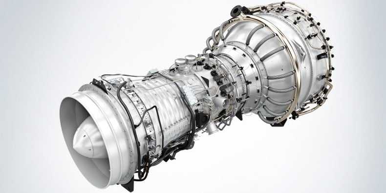
Apart from these common models, which are often called ‘Industrial Gas Turbines’, there are also advanced models available (see above).
These aeroderivative gas turbines come – as the name implies – from the aircraft construction industry, i.e. they have been derived from an aircraft engine and stand out for their more compact design compared to industrial gas turbines which are designed for conventional applications in power stations.
Safeguarding Electrical Power Supply as Main Area of Application
Aeroderivative gas turbines are mainly used for reliable power generation at peak usage times in power stations, for safeguarding emergency power supply, but also for local energy supply, among others in combined heat and power plants.
During the Olympic Winter Games 2014 in Sochi, for example, two General Electric aeroderivative gas turbines, i.e. derived from aircraft engines, with an output power of 100 MW each, provided for the reliable supply of electric energy. These turbines stand out for their quick start ability, reaching full power in less than 10 minutes.
Use of Couplings
In addition to their application in the energy supply industry, aeroderivative gas turbines are also used for driving compressors or pumps. This often requires that the operating speed of the turbine is adapted to the specific speeds of the driven machine, i.e. to increase the speed (e.g. if centrifugal compressors are involved), or to reduce the speed (for instance, in the case of generators).
Basic Selection Criteria
Unlike the standard design of a coupling, e.g. for a reciprocating engine, additional factors have to be taken into consideration when the coupling is intended for use with an aeroderivative gas turbine. Aside from the occurring transmission torques (peak torques) and the usual torsion-critical analysis, critical bending moments have to be taken into account, too.
Couplings for use in gas turbines need to have a high balance quality. This necessitates a torsional stiffness and a bending stiffness as well as a need for components to be designed as lightweight as possible. Furthermore, the particular sensitivity of an aeroderivative gas turbine plant requires a coupling that exerts as minimal reaction forces and moments as possible, for example due to thermal length growth (radial and axial).
The gas turbine and the driven machine are generally coupled directly or by means of a gear unit, depending on the application. Three coupling types are normally used:
- Gear couplings
- Disk couplings
- Diaphragm couplings
These couplings differ in configuration, the transmittable torque and in their capability of axial misalignment and angular displacement. In the following we explain which pros and cons the different coupling types have for you and your application.
Use of Gear Couplings
 On account of their compact design, gear couplings have been preferably used in the past. Gear couplings feature a comparatively high power transmission capability and are able to compensate alignment faults during installation (angular misalignment, radial offset) and during service. Here you have to particularly take into account that the resulting reaction forces which have an impact on the gas turbine and/or the plant components are decisively influenced by the lubrication condition of the coupling.
In contrast to other coupling types, gear couplings are relatively insensitive to torque shocks which may occur, for instance, when a plant is started or stopped.
The use of a gear coupling, however, has the disadvantage that you have to monitor the lubrication condition of the gear teeth as well as their wear rate, which means higher maintenance efforts and a limited useful life of this coupling type. Moreover, on account of the required tooth flank and tip backlash, today’s high demands in terms of high-precision balancing can only be met to a limited extent.
Disk Couplings
 For the above reasons, disk couplings , which stand out for their relatively high angular and radial misalignment capability, offer themselves as an alternative. They also stand out for their relatively high angular and radial misalignment capability. Moreover, disk couplings are not subjected to wear as no backlash exists, and they do not need lubrication. Therefore, disk couplings are maintenance-free.
In regards to misalignments you can more precisely determine the occurring reaction forces and –moments.
The power transmission capability of the coupling is basically defined by the number of disks, i.e. the more disks are installed, the higher the torque that can be transmitted. However, you have to take into account that the increase of the disk number simultaneously decreases the angular misalignment capability and increases the reaction forces.
Another important advantage of disk couplings is that even in the event of an impermissibly high overload, only individual disks break. Thus, the continued transmission of the torque is still ensured. By monitoring parameters such as vibration levels, coupling damage can be safely detected with relative ease.
Diaphragm Couplings
Compared to the above-mentioned two coupling types, diaphragm couplings features particularly high balancing qualities so consequently are able to fulfill very high requirements in terms of bending vibrations.
This particularly applies to installations where very high speeds and very long distances between the drive and the driven machine are involved.
At diaphragm couplings you can determine the reaction forces and –moments also precisely beforehand. In addition, the diaphragm coupling is able to accommodate axial displacements of up to 25 mm.

Post image: www.siemens.com/press

Comment