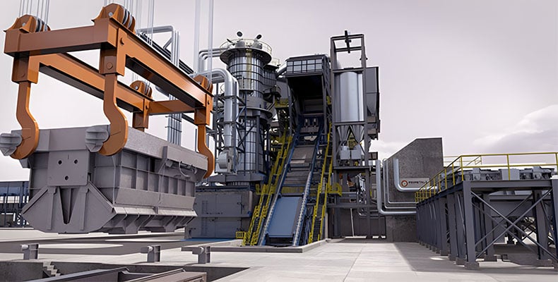
In the energy-intensive steel production industry, Primetals is setting new standards for sustainability with the EAF Quantum Furnace. Through innovative technology and an integrated heating system for processing steel scrap, energy consumption is minimized, and CO2 emissions are reduced. Learn more about this groundbreaking solution for an environmentally conscious steel industry.
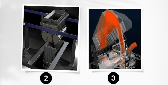
This system can process steel scrap of varying compositions and qualities. Compared to conventional electric arc furnaces, the electricity demand here is extremely low, partly because an integrated heating system preheats the scrap. This reduces both operating costs and CO2 emissions. Combined with reduced electrode and oxygen consumption, there is an overall advantage of around 20% in specific conversion costs. Compared to conventional electric arc furnaces, the overall CO2 emissions can be reduced by up to 30% per ton of raw steel. The metal scrap is loaded into a container, which is part of an automatic scrap charging system at the bottom of the furnace (Image 2). The container is lifted to the top of the furnace and unloaded (Image 3).
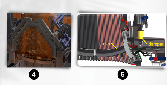
The scrap falls from a great height onto the scrap retention system (Image 4). This system is located directly above the melt, which preheats the scrap through its direct heat and a heat recovery system. It consists of 6 opposing fingers (Image 5), each with a buffer installed with RINGFEDER® friction springs at their outer ends. When a temperature of 600°C is reached, the finger system opens, and the scrap falls into the melt. The buffers provide flexibility to the system and protect it from damage when the impact energy generated by the falling scrap is released.
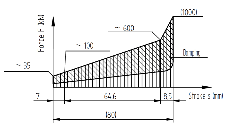
At the beginning of the project, it was not definitively defined how much mass would hit the fingers with each deposition. For this reason, dampers with a single spring of type 24201 with a maximum force of 1000 kN were initially designed. The diagram values would have allowed a maximum operating load of 740 kN with a spring travel of 62 mm, a preload of 100 kN, and a capacity of 47,500 joules. They were also designed so that an additional parallel spring of type 19600 could be added later if the released energy was higher than originally calculated. After further calculations, it was found that the actual energy absorption required was significantly lower. The final version includes the series connection of the mentioned types 24201 and 19600, resulting in a stepped characteristic curve in the diagram in consultation with the customer.
The system has proven itself, and we have supported our customers with this product since 2013. This once again demonstrates that RINGFEDER® friction springs can be used in various environments under extreme conditions.


Comment