The coupling is normally the softest element in the drive line, literally – but by no means the weakest link of the chain. Its configuration plays a decisive role for the functional capability of the driving and driven machine and for the reliability and lifetime of the entire drive system. The optimum adjustment of the coupling to the connected machine units is especially important in all cases where failures and breakdowns are not allowed to occur.
The dynamical characteristics of a coupling have an effect on the natural frequencies of a machine unit, and as to whether resonances are likely to occur in the operating speed range. The critical resonance state is reached when the system is excited at one of its natural frequencies (depicted in Fig. 1). The entire system swings up and this will lead to an increase in the amplitude. This puts additional loads on the components and lead to system or material failures. High costs for replacement parts and frequent maintenance operations are the consequences.
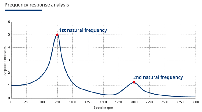
Fig. 1: Frequency analysis with presentation of the 1st and 2nd natural frequency along with the corresponding amplitude ratios.
For drives using combustion engines it is common to use a coupling that is designed to allow the plant to be continuously operated even in non-optimal speed and torque ranges. This is mainly achieved by the optimal adjustment of the stiffness so that the natural frequency is shifted into less critical speed ranges. Every drive system operates in an optimal manner, and hence is not subjected to damage or failure, if stiffness and damping are tuned individually. It is only with the advent of this new generation of highly flexible couplings that this flexibility is possible because of one distinctive feature: the spatial separation by arranging the elastomer buffers in series. This allows to ideally tailor the stiffness to the requirements of the application by adeptly selecting the available elastomers for the inner and outer buffer rows.*
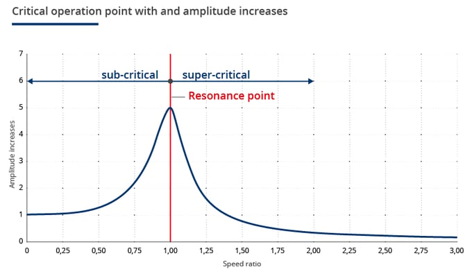
Fig. 2: Sub- and super-critical operation point with corresponding amplitude ratio.
Three example applications to show why it is beneficial to use these couplings
Example 1: The combined heat and power plant
A combined heat and power generation plant may be equipped with different drives. A CPH manufacturer offering 15 different combined heat and power units which, for instance, are configured by the combination of three engines and five different generators, also needs up to 15 suitable couplings for being able to optimally adjust the torsional vibration behavior of each unit. For storage reasons and to keep the maintenance operations to a minimum, this is seldom the case in practice. In fact, compromises in terms of vibration behavior are made.
With an individually adjustable coupling which is equipped with replaceable elastomer buffers, the manufacturer only needs one single coupling and uses different sets of elastomer buffers in order to satisfy specific requirements. Hence, the attached parts remain the same, and only the buffers need to be changed. In addition to saving inventory costs, the manufacturer is able to supply its customers with an optimally tailored drive with an individually adjustable coupling. This results in a long equipment lifetime and low maintenance costs.
Example 2: The emergency power unit
High demands in terms of reliability, safety and long service life are made on emergency power units in hospitals or offshore platforms. Yet, in particular large power generators are difficult to adjust with respect to their resonance vulnerability. The required stiffness is generally determined by calculation. If, however, deviations are observed during real operation conditions compared to the simulated model, there is only one way to solve the issue in case a conventional disc coupling is installed: the operator has to replace the entire coupling.
The individually adjustable coupling with replaceable elastomer buffers offers a second option to the operator: the step-by-step optimization of the design by replacing individual buffers. This will save time and costs.
Example 3: High-power drive systems
This again refers to large systems, that is, engines with a power above 1000 kW. If the coupling is not correctly designed in terms of stiffness and damping, uneven operation and vibrations can be the result. Contrary to stand-by power generators for which no risks are generally taken, production facilities and other applications attempt to counter-act resonance phenomena by using a torsional stiff coupling design. The operator thereby accepts the risks of higher costs and maintenance efforts for the replacement of the coupling, as well as more frequent and longer breakdowns of the equipment.
If, however, the operator uses an individually adjustable coupling with replaceable elastomer buffers, the step-by-step optimization of the entire system will be possible.
* From: Untersuchungen an seriell angeordneten Elastomerelementen in Wellenkupplungen mittels der Finite Elemente Methode)/ Beuth Hochschule für Technik; Berlin (Studies on elastomer elements arranged in series in shaft couplings by means of the finite element method/ Beuth University of Applied Sciences; Berlin.)

Comment