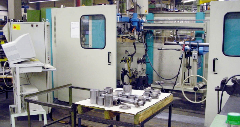
Company-owned balancing machine in Neunkirchen, Germany
A virtually rotational-symmetrical component may have an unbalance caused by production tolerances or non-homogeneous structure in the material. Such unbalances in a drive system can not only lead to considerable vibrations during operation, but, in the long run, can also lead to failures of individual components or even of the entire drive system. As speed constitutes one of the decisive influences here, balancing is always performed for a certain speed. As a general rule, this is the nominal speed of the drive system.
The necessity of balancing
In order to prevent unbalance and to protect the drive system, the respective component, e.g. a coupling, must be balanced. The former standard DIN ISO 1940, which had been specifically published to cover this subject, has recently been technically revised and renamed to DIN ISO 21940-11. With the help of the following example of a shaft coupling, we would like to provide you with some insight into the topic of balancing.
Static and dynamic balancing of a rotor
Concerning balancing, a distinction is made between “static” balancing (the so-called one-plane balancing) and “dynamic” balancing (the so-called two-plane balancing). The decisive criterion for static or dynamic balancing is the length/diameter ratio of the rotor to be balanced (e.g. the entire coupling or components of a coupling). If the length/diameter ratio is <= 1, static balancing takes place. If the length/diameter ratio is >1, dynamic balancing is done. The unbalance at a rotor can be corrected by removing material, for example, by drilling or grinding off material. On the other hand, material can be added, e.g. by welding or bolting on material.
 Types of unbalance
For static balancing, it is sufficient to correct the unbalance at the rotor in one plane only, i.e. mass is only compensated for in one location on the axis of the rotor. With dynamic balancing, the unbalance is corrected in at least two planes or several planes at the rotor.
Particular considerations when balancing a shaft coupling
The balancing method is selected depending on the coupling type and its configuration. There are four different balancing methods:
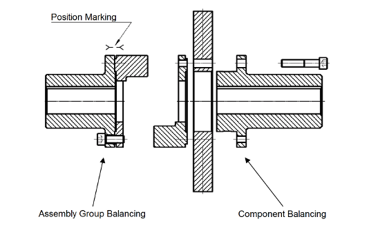
1. Component balance
Individual components or all the parts of a coupling are balanced separately in accordance with the specified balance quality.
2. Sub-assembly balance
Individual components of a coupling are assembled to form one sub-assembly, e.g. left or right coupling half, which is balanced in accordance with the specified balance quality. The individual components of the sub-assembly are then match marked to guide future assembly.
3. Combination of component / subassembly balance
In this method, e.g. one coupling half is balanced as a sub-assembly whereas the components of the other half are individually balanced. This allows to interchange wear parts such as brake disks or drums without any problems at a later point of time.
Combination of component / subassembly balance
4. Assembly balance
The balancing of completely assembled couplings is only pertinent to torsionally rigid couplings or backlash-free couplings, e.g. disk or metal bellows coupling. This method provides for the compensation of all errors/tolerances at the interfaces of the coupling components. Optionally, individual parts and/or sub-assemblies are balanced beforehand in order to minimize the need for unbalance correction during the assembly balance.
Gear couplings generally cannot be balanced as a complete assembly, because the hub and the sleeve are not concentric to each other on account of the clearance in the tooth mesh. The hub and the sleeve are not centered until they are under load, and this condition is not given during balancing. For this reason, gear couplings can only be balanced in individual components or sub-assemblies.
An assembly balance for elastomeric couplings is not appropriate because the elastic intermediate ring or the elastic buffer always act as the “resilient, deformable section point” between the two coupling halves. Under operating conditions, the ring will deform differently than during the balance procedure, and can, therefore, not be determined as a component for balancing.
Full-key and half-key balancing of shaft couplings
Shaft couplings connect the drive and driven machine, or the gearboxes installed in between them. These units are also balanced by the manufacturers. There are different balancing methods for shafts intended to be used as a shaft-hub connection with a key. The distinction is made between half-key balance and full-key balance. In order that the balance of the shaft and that of the coupling are compatible, the respective key convention must be considered for balancing the coupling.
For the half-key balance, the machine shaft is balanced with an inserted half key or before the keyway is machined. In this case, the coupling will also be half-key balanced. For this, the coupling sub-assembly or the coupling component is drawn onto a fixture (shaft) and balanced with a filled keyway. The keyway can either be filled with a half key, or the coupling is balanced prior to keywaying.
The latter is the more common and easier method because the exact location and weight of the key must be known when balancing with an inserted half key is performed. These details are often not available in advance, and this procedure is quite complex, too.
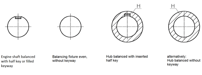
Half-key balance
With full-key balance, the machine shaft is balanced with an inserted full key. In this case, the coupling is drawn onto a balance fixture after the keyway has been machined, and is then balanced with an empty keyway.
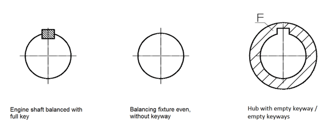
Full-key balance
As mentioned above, it is essential to balance a coupling to ensure that your drive system runs without unbalance and that the components are protected. The selection and design of the correct coupling are, of course, also of great importance. We would be happy to help you find the optimal coupling for your application.


Comment