Locking Assembly Eliminates Bending Moment Failures
Bending moments are an unfortunate fact of life in many power transmission applications. But pulley-and-drum systems have an especially high risk of failure when exposed to these moment loads.
But not all locking assemblies are properly designed when it comes to withstanding bending moments, resulting in premature failure. Here’s a closer look at what causes those failures and how to avoid them.
Weak Locking Assemblies Fail. Any flexion in drum or pulley shafts will generate bending moments that create high stresses within the locking assembly. These stresses are not equally distributed through the assembly, which leads to two distinct failure modes:
- One side of the locking devices will experience very high stresses, sometimes to the point that they exceed the yield strength of the materials used for the locking device.
- The other side of the locking device will see lower forces from the bending moment. But the low force side tends to lift away from the shaft. This lift is almost imperceptible, but it’s enough to allow small sliding movements between the locking device and shaft. The result is a fretting wear that can ultimately destroy both the locking assembly and shaft.
Robust Locking Assemblies Survive. So how do you avoid these two types of bending moment failure? The answer is simple: Make sure you specify a locking assembly that has been designed specifically to tolerate bending moments. We provide three distinct design differences:
First, our design for these bending moment applications, for example, uses materials with yield strengths up to 40% higher than a standard locking assembly.
Second, our designs for high bending moments also tend to be wider than a standard locking assembly—because wider assemblies inherently have a higher resistance to the moment forces and will be less likely to lift away from the shaft.
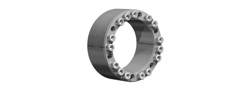
Lastly, we optimize the number and location of bolt holes in the locking assembly’s pressure ring. By reducing the number of bolt holes but putting them in the right locations, we can substantially improve the locking assembly’s ability to resist moment loads—in part, because bolt holes reduce the working stresses the assembly can tolerate.
Added Benefits. These design enhancements that help with bending moments also have an added benefit related to component sizing and cost. Usually, the locking assembly’s bending moment capability determines the shaft size. So if you upsize the locking assembly based on moment loads, you’ll also have to upsize the shaft and its bearings. And that type of engineering can be costly.
By using a locking assembly that’s designed for high bending moments, you can often use a smaller unit, allowing for similar reductions in shaft size.
Try the Ringfeder Calculation Tool to calculate the bending loads for your application.
The reason relates to the locking assemblies that connect the drum or pulley to a rotating shaft. As the preferred shaft connection method for these systems, properly designed locking assemblies can run trouble-free in pulley and drum systems for years.

Comment